For the optimal design of inductors and inductive hardening processes including the frequency converter as their energy source, we apply targeted analysis methods and numerical simulation tools. We use these, among other things, to advise you on the feasibility of the induction heating process for your heat treatment requirements, as well as to evaluate and optimize it in terms of efficiency and practical feasibility.
In the following, we will explain the possible applications of our numerical simulations and their advantages in connection with induction heating.
Take advantage of our expertise in simulations and numerical calculations. We offer these as a service, also independent of plant-related inquiries and orders.
In heat treatment, heating by means of induction technology offers many advantages, among other things because the heat is generated directly in the respective component. In comparison, heat treatment with 'classic' industrial furnaces requires a carrier medium in the furnace atmosphere to transfer the energy to the component by means of heat transfer.
There is one prerequisite for induction heating on the material side: the component must be made of electrically conductive material. Since many components are made of metal and almost all metals are electrically conductive, several components are suitable for induction heating. Further applications can also be found with non-metallic conductive materials such as glass or graphite.
In simplified terms, induction heating works like this:
The most important influencing variables for tailoring the heating effect to the desired result are, for example, the geometry of the inductor, the distance between the workpiece and the inductor (coupling distance), the use of concentrator material (for the local amplification of the magnetic field), the frequency and the current intensity.
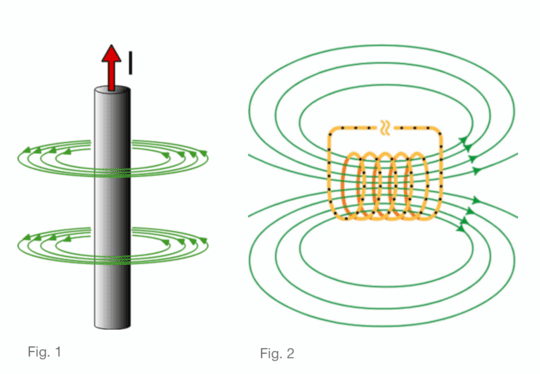
Every electric current that flows through a conductor generates a magnetic field (see Fig. 1). This magnetic field can be represented according to the so-called 'three-finger rule' (or also 'right-hand rule'): If the conductor is held with the right hand, the thumb points in the direction of the current and the curved fingers indicate the direction of the magnetic field lines.
To concentrate the magnetic field, a copper conductor, for example, is wound cylindrically into a coil (see Fig. 2). The magnetic field is the strongest at the center of the coil, resulting in a higher heating effect in this region.
Fig. 1: Every current-carrying conductor builds up a magnetic field.
Fig. 2: Amplification of the magnetic field occurs within a coil.
Choosing the correct Inductor shape is an important criterion in determining the overall efficiency of the Induction Heating process. Considering a cylindrical workpiece such as shafts, tubes, etc., a cylindrical shaped Inductor is well suited since there is higher coupling between the workpiece and the Inductor.
In induction heating, the heating in the component results from
The type of heating described above is a complex and highly nonlinear process. Various parameters and side effects have to be taken into account, e.g. the emergence of the magnetic field, the interaction with the component, also referred to as "coupling" of the magnetic field, the emergence of the induction currents in the component, the consideration of the current displacement effect (skin effect) as well as the penetration depth and temperature-dependent material properties.
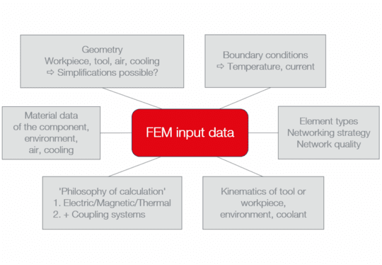
These influences factors can be estimated via the empirical knowledge of process experts. However, due to the higher complexity, in processes or a complex geometry of the workpiece, there are certain limitations. These limitations can be overcome by. Modern calculation methods such as computer aided engineering (CAE). For this purpose, a mathematical model of the induction process is built up, based on the CAD data, and the process boundary conditions are defined for each component, such as
The model is then meshed using the finite element method (FEM). Meshing (also called discretization) is of great importance for realistic calculation. In the process
are discretized. Taking heating and transport times into account, the induction process can then be calculated (see Fig. 3).
On the basis of the model created, the strengths and advantages of CAE simulation come into play: time-, personnel- and material-intensive test series such as achieving the optimum results with respect to
can be executed virtually with little effort. On the one hand, this leads to a deeper understanding of the processes and, on the other hand, to new insights and possibilities and ‘out of the box’ approach. The concerns regarding the
are also the focus of attention.
In additive manufacturing – i.e. the production of inductors using the 3D printing process – simulations also offer added value: Using simulation, a particularly promising inductor variant can be determined in advance of 3D printing. In addition to process reliability, this offers major advantages for targeted development "to the point" for both the energy supply and the process.
In order to achieve a certain hardness level in the component, the geometric penetration/heating depth is of decisive importance: To achieve higher hardness levels in the workpiece, the workpiece (assuming it is steel) must contain Martensite phase which is a Body-Center Tetragonal (BCT) structure. To obtain this Martensite phase, the workpiece needs to first be austinitised (phase transformation from ferrite to austenite) and then rapidly cooled to obtain the needle-shaped grains known as Martensite.The heating of the workpiece to austenisation Temperature is a prerequisite to create a hardness zone and the subsequent cooling time can greatly influence the hardness level of the workpiece.The geometric expression of the martensite zone and the absolute hardness is strongly application-dependent.
Martensite is characterized by high hardness and is often used in components that are subjected to tribological loads. Martensite-hardened components have excellent hardness values, which in turn enables great wear resistance. Using CAE analysis the hardening process can be replicated, optimised and also improve the process efficiency.
The frequency is not a direct setting variable at the frequency converter. It results from the resonant frequency of the oscillating circuit, consisting of the inductance in the heating process, and the installed capacitance in the power supply.
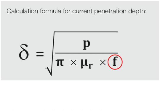
The frequency has a decisive influence on the position of the induced current and thus on the generation of heat in the component. If the material of the component is known, the current penetration depth δ can be calculated using this calculation formula.
Apart from the material-specific parameters p and µr, the frequency is the only free variable. This means that at high frequency the penetration depth decreases:
Fig. 4: Calculation formula for current penetration depth; source: Schreiner, A; Irretier, O (eds.): Praxishandbuch Härtereitechnik; Vulkan-Verlag GmbH, 2013; p. 223
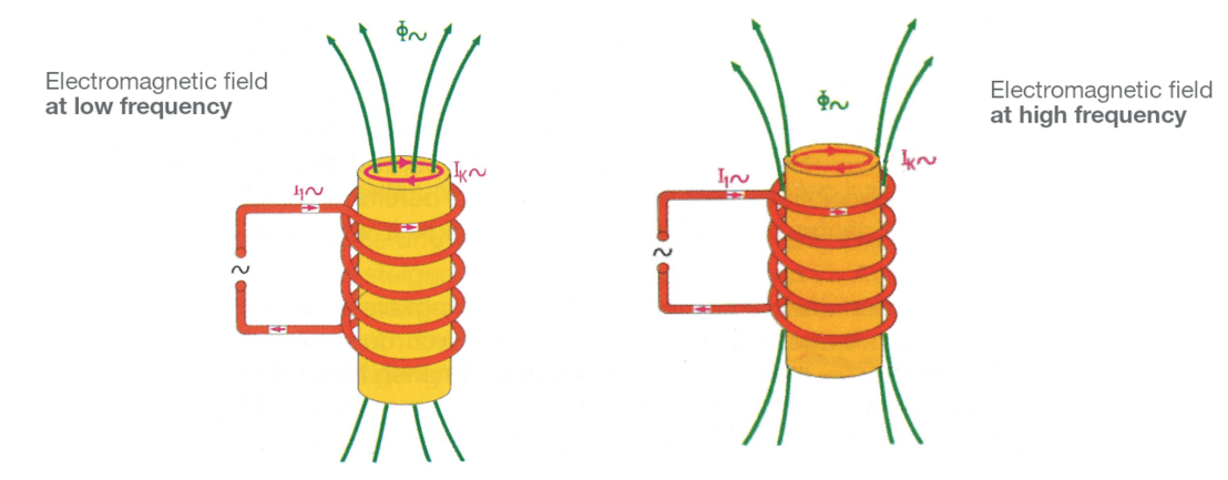
This can be seen schematically in figure 5 below:
On the left the field lines at low frequency are shown, on the right the field lines at high frequency.
(Source: Schreiner, A; Irretier, O (eds.): Praxishandbuch Härtereitechnik; Vulkan-Verlag GmbH, 2013; p. 223)
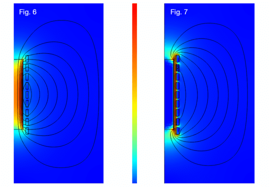
In the calculation using CAE, the penetration depth can be illustrated:
This relationship is of great practical relevance for the heating zone and thus for the hardening zone. If the task is to harden very close to the surface layer, a high frequency should be selected. But what is high enough?
The mains frequency in private households is 50 Hz. This means: 50 times per second the current changes direction. At 1000 Hz (1 kHz), the current and thus the magnetic field changes direction 1,000 times per second. That should be very high, right?
This is demonstrated below using the example of a gear wheel. Depending on the penetration depth, the induced current flow tends to be located close to the contour or at the bottom of the tooth.
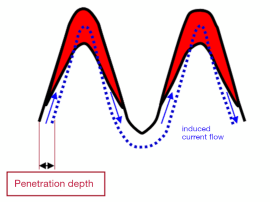
Fig. 8:
low penetration depth, current flows close to contour
=> Heating of the tooth tips
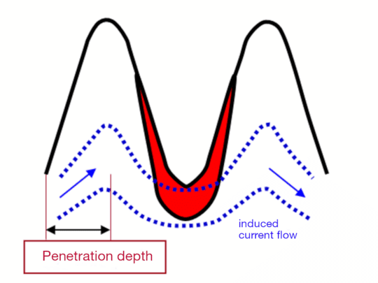
Fig. 9:
high penetration depth, current path at the base of the tooth
=> Heating of the tooth root
This means: For each
different results are obtained for different heating times. This is where CAE comes into focus again.
By the following example – an outfield inductor equipped with a concentrator – the above explained principle can be shown for an inner toothing in the CAE simulation:
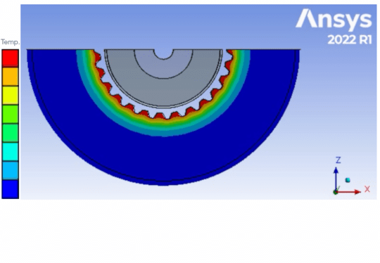
For the relatively high frequency of 1,000 Hz, the tooth root is heated to a maximum. However, the tooth tip and the tooth flank would not be hardened. This may be intentional.
Fig. 10 CAE: Temperature in the toothing at 1,000 Hz
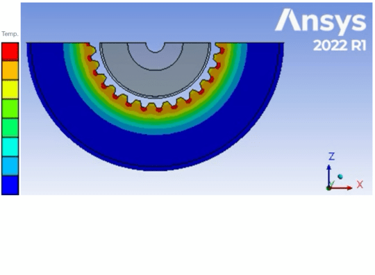
When the frequency is increased to 200,000 Hz, the temperature picture is mathematically different: Here, the tooth tips show the highest temperatures in each case. In combination with prompt quenching, a hard martensitic microstructure could be realized at the high temperature. For a high tribological load, i.e. high forces and relative movements on the tooth flanks, this temperature pattern would be much more suitable.
Fig. 11 CAE: Temperature in the gearing at 200,000 Hz
Experimental tests are of great importance for the verification of the calculation results. Only when the experiment fulfills the calculated relationships can a "correct" CAE analysis be assumed in further analogous analyses. Therefore, basic verification tests are necessary, especially for new materials and innovative inductor shapes and novel calculations approaches.
The penetration depth depending on the frequency was performed on identical gears for 20 kHz and 200 kHz respectively. The hardening zones are visible in the figure below (see dark areas). They were set by rapid cooling of the same design.
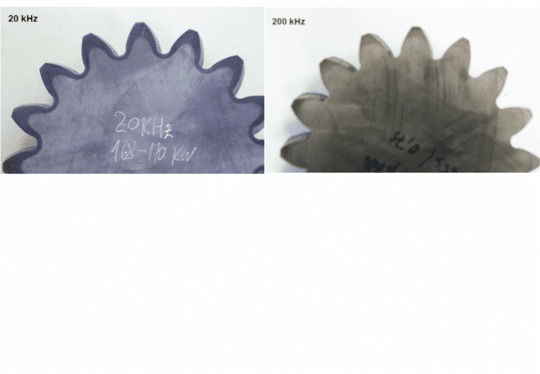
In the example of 20 kHz (left), near-contour hardening was achieved along the outer contour of the tooth.
On the right, only the tooth tips were hardened at a tenfold frequency of 200 kHz.
Fig. 12: Influence of frequency on the hardness zone using the example of a gear wheel
Do you have questions about simulation methods or would you like to use our expertise for the optimal design of inductors and frequency converters? We are happy to support you with your challenges. Contact us with your requirements and we will get back to you shortly.